How Do Jet Engines Work?
Modern aircraft are powered by gas turbine engines that pass air through a series of stages where it is compressed, ignited, and expelled. This process creates a high-pressure exhaust that is used to drive rotating engine parts and produce thrust.
Posted: August 30, 2017
By:
Powered by Air
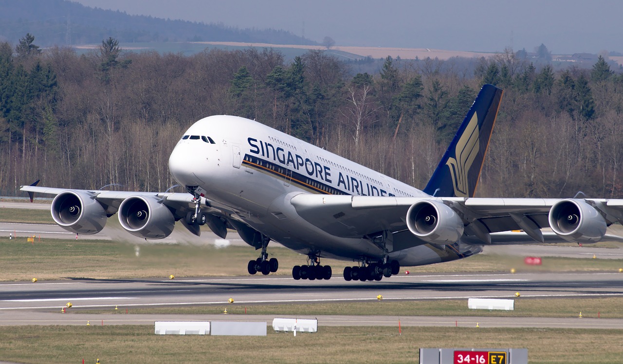
Aircraft require tremendous engine power to achieve liftoff and flight. A fully-loaded Airbus A380 – the largest passenger jet in operation – can weigh over 500 tons at takeoff, requiring four massive engines combining for 300,000 pounds of thrust.
The engines need to propel the plane fast enough to generate sufficient lift to overcome the force of gravity. But unlike land vehicles that push against the ground with powered wheels, aircraft generate thrust via propellers or engines that push against the air.
Gas turbine engines are filled with airfoils or “blades” of varying sizes attached to a rotating axle. The blades move air through the different stages of the engine, compressing and expanding the gas to produce thrust that propels the plane forward.
What does a gas turbine engine look like?
Below is schematic of a typical gas turbine engine. The air intake on the left is often accompanied by a large fan to increase suction. The air is then compressed to a smaller volume before being mixed with fuel in the combustion chamber. The mixture is ignited by a spark or flame, and the hot gas passes through a turbine that spins to power the compressor and fan. High pressure exhaust then passes out the back of the engine, producing thrust and propelling the plane forward. The stages of a gas turbine are outlined in more detail below.
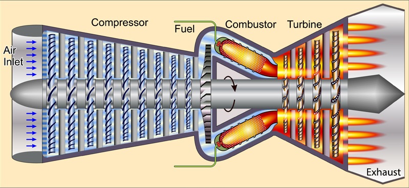
Stages of a gas turbine jet engine
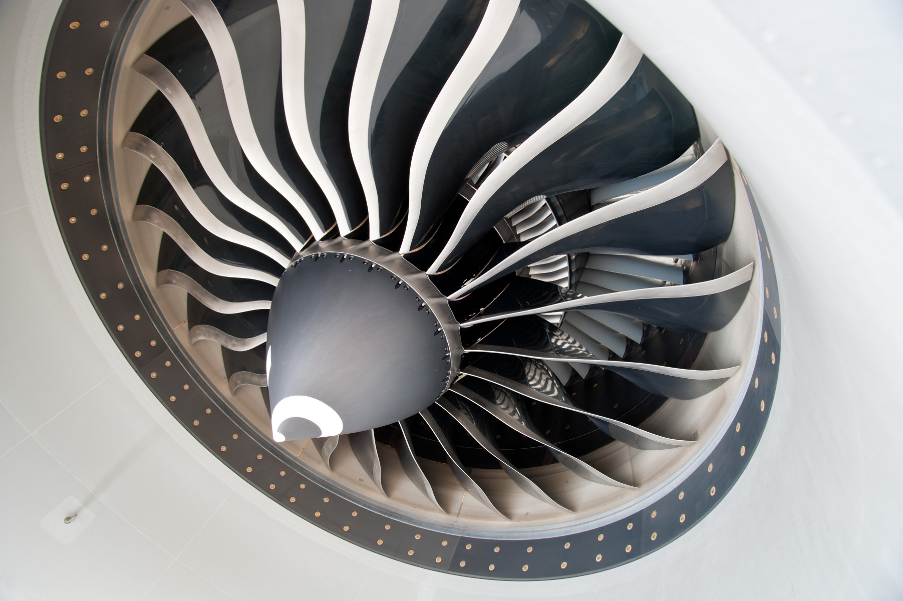
Fan: The fan is located at the front of the engine and is the primary air intake. Large spinning blades suck in vast quantities of air, accelerating the gas and splitting it into two separate streams. Some of the air is directed around to the rear of the engine to produce thrust, while the rest is channeled into the engine’s core where it enters the next stage.
Compressor: The compressor squeezes the air drawn in by the fan blades, compressing it into a smaller volume and increasing the pressure. The compressor section is lined with multiple rows of blades that force the air into progressively smaller channels. Compressing the air increases the potential energy, and concentrates the oxygen molecules for more efficient combustion in the next stage.
Combustor: The combustor introduces fuel into the compressed air and ignites the mixture, creating a high-pressure expanding gas. This is the hottest section of the engine, where energy is released from burning fuel and temperatures can climb over 2,000 degrees Fahrenheit. The combustor is lined with fuel-injecting nozzles and an igniter to spark the reaction. Once ignition occurs, a steady stream of fuel ensures combustion is maintained, and the expanding gas is directed downstream into the turbine section.
Turbine: The turbine section is another series of rotating blades that are driven by high-pressure air leaving the combustor. The turbine blades catch the rapid airflow, and rotate to drive a spinning shaft that turns the fan and compressor at the front of the engine. The turbine essentially powers the rest of the engine, harnessing energy from the combustion chamber to maintain steady air intake and compression. Air passing though the turbine loses energy to the rotating blades, but what remains moves into the final exhaust stage of the engine where it is expelled to produce thrust.
Nozzle: The nozzle is the cone-shaped duct at the rear of the engine. Here the airflow from the engine core and the bypassed air from the fan section are expelled to produce thrust. The engine nozzle is usually tapered to accelerate the escaping gas, and the air exiting the nozzle exerts a force on the engine that propels the aircraft forward.
Some engines employ an afterburner to generate additional thrust. The afterburner injects more fuel and ignites the mixture after it has passed through the turbine. The process significantly enhances the velocity of air exiting the nozzle, but it consumes excess fuel and is only employed for brief periods on specialized military aircraft.
How Does a Jet Engine Work – Video Summary
Here’s a fun video produced by CFM International that follows animated air particles through each stage of a high-bypass turbofan engine.
Airfoil Enhancement
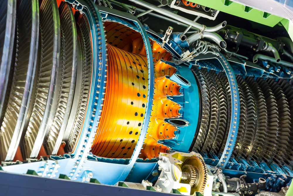
A single jet engine can have hundreds of blades within the fan, compressor and turbine sections. These blades vary in size, shape, and material composition, but they all perform critical functions in the engine’s operation. Given the extreme forces and temperatures present within a gas turbine engine, metal enhancement techniques like laser peening are vital to the safety and performance of the engine and its components.
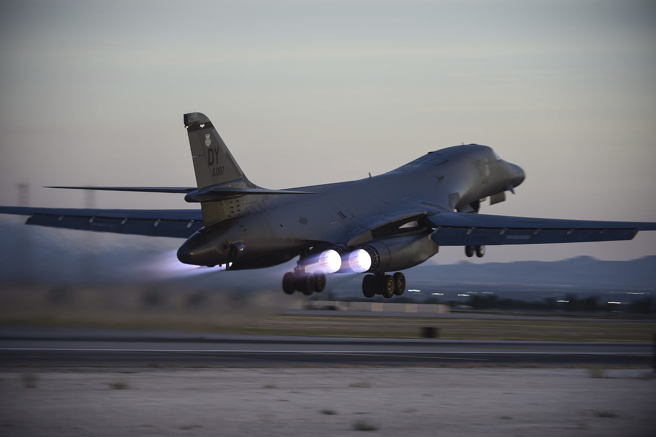
FOD Resistance: Foreign object damage (FOD) is a serious hazard for aircraft engines. The powerful suction created by the fan and compressor can pull in hard objects like ice chunks or runway debris, potentially damaging engine components. Laser peening provides unparalleled FOD resistance, and has been shown to significantly impede the cracking and fracture associated with FOD in titanium fan blades. Laser peening has been employed for more than 20 years to protect critical engine components in the B-1 Bomber.
Fatigue Crack Prevention: Fatigue cracking is another major hazard for aircraft engine blades. As the components rotate at high speeds, each blade experiences tensile stress that repeats for millions of cycles. If a crack develops in the metal, even at a microscopic scale, the repeated loading of each cycle can progressively widen the crack until it grows so large that the blade fractures. Laser peening is often applied to fan, compressor, and turbine blades in areas that are prone to cracking and fatigue. The deep compressive residual stresses imparted by laser peening impede crack initiation and propagation, extending the service life of blades and preventing unexpected failures.
Next week we’ll discuss the different types of aircraft engines: From turbofans and turboprops to ramjets and scramjets.
Follow us on LinkedIn so you never miss an article or blog.
Contact LSPT to learn more about laser peening gas turbine engine components.
Interested in Seeing More?
Tell us about your application, material, or failure mechanism and we will have one of our experts reach out to you. Our extensive library of research and years of experience gives us a unique advantage to apply a finite element analysis to help diagnose the best application for your situation.